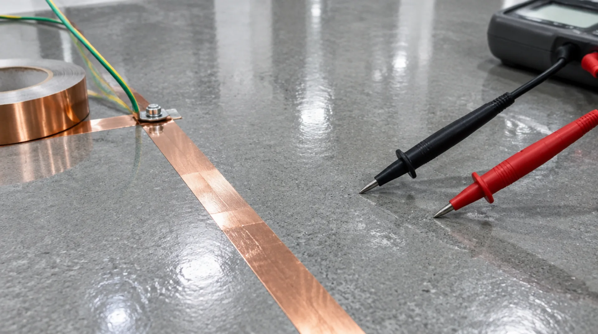
An epoxy floor conducts because a carbon-based additive is mixed into the resin before it cures, not because of anything added afterward. That conductive resin is then tied into a copper grounding grid bonded to the building's electrical ground, and the finished system is verified with a megohmmeter against ANSI/ESD S20.20 resistance ranges before it goes into service. Get any one of those three steps wrong and the floor can look identical to a correctly built one while failing its first resistance test.
What makes an epoxy floor conductive in the first place
A standard epoxy coating is an electrical insulator. Conductivity is engineered in by dispersing a conductive filler through the resin at the formulation stage, so the additive becomes part of the cured film rather than a surface treatment applied afterward. The result is a coating that carries static charge away from whatever is standing or rolling on it, down through the film, and out to a grounding point rather than letting it build up on a person, a cart wheel, or a component tray.
This is the detail that separates a genuine ESD floor from a floor that merely looks the part. Two charcoal-gray epoxy floors can be visually indistinguishable while one measures in spec and the other reads as an open circuit, because the difference lives inside the resin, not on top of it. If you need the broader case for why that distinction matters for electronics and defense work, our guide to ESD epoxy flooring for electronics and defense facilities covers the compliance side in more depth than this post does.
Carbon fiber versus carbon black versus nickel-coated additives
Three families of conductive filler cover nearly every ESD epoxy system installed today, and they are not interchangeable even though all three show up in the same resistance range on a data sheet.
Carbon fiber is milled into short strands and dispersed through the resin, where it forms a network of overlapping conductive paths. It is the most common choice for mid-range static dissipative systems because it gives predictable, repeatable resistance without pushing the floor into the fully conductive range unless the loading is increased.
Carbon black is a finer particulate additive, more commonly used where a lower, more conductive resistance range is specified. Because the particles are smaller and more numerous per unit volume, carbon black systems tend to reach conductive-range resistance at lower loading than carbon fiber, but the tradeoff is a flatter, less glossy finish and in some formulations a slightly more brittle film.
Nickel-coated graphite or carbon fillers sit at the premium end. The metal coating improves particle-to-particle contact, which gives more stable readings across a floor and better performance in high-humidity or high-temperature environments where other fillers can drift out of range. They cost more per gallon, and specifiers reach for them on critical floors such as defense manufacturing cleanrooms where a resistance drift is not an acceptable outcome between audits.
None of these fillers can simply be stirred into an off-the-shelf epoxy on site. Loading rates, dispersion method, and cure chemistry are matched by the manufacturer to produce a predictable, tested result, which is why conductive systems are sold as matched kits rather than as an additive you add to a standard product.
The copper grounding grid: layout, spacing and tie-in to building ground
Conductive resin alone does nothing without a path to earth. Every ESD floor system is built over a grid of copper grounding strips embedded at the primer stage, before the body coat goes down, so the strips end up buried inside the film rather than sitting on top of it.
The strips are typically laid in a crosshatch pattern at intervals the manufacturer specifies for the square footage being covered, commonly somewhere in the 10 to 20 foot range between runs, with closer spacing in rooms carrying the most sensitive equipment. Each strip run terminates at a ground point, usually a copper lug bonded to a dedicated grounding conductor that ties back to the building's electrical ground through a resistor, which limits fault current while still allowing static charge to drain continuously.
The number of ground points is driven by floor area and by the specific ANSI/ESD standard the facility is certifying to, not by guesswork. A small lab might need only two or three tie-in points, while a large manufacturing floor can require a dozen or more distributed across the grid so that no single point of the floor is more than a specified distance from a ground connection. Skipping or under-specifying ground points is one of the more common reasons a floor reads correctly in some spots and fails in others.
How a conductive primer, body coat and topcoat stack up as a system
An ESD epoxy floor is built in three layers, and conductivity has to survive through all three or the finished floor will not meet spec even if the grounding grid and the resin chemistry are both correct in isolation.
| Layer | Function | Conductivity role |
| Conductive primer | Bonds to the slab, embeds the grounding grid | Makes first electrical contact with the copper strips |
| Conductive body coat | Builds film thickness and durability | Carries the bulk conductive load across the floor |
| Conductive or clear topcoat | Adds wear resistance and finish | Must stay thin and conductive, or it insulates the floor |
The primer coat is where the grounding grid gets its first electrical contact, so primer coverage over every strip matters as much as primer adhesion to the slab. The body coat is what most people think of as the floor itself, carrying both the bulk conductive load and the majority of the mil thickness. The topcoat is the layer most often responsible for a floor failing after it initially passed, because a non-conductive sealer or an over-applied conductive topcoat can insulate the system from above even though the primer and body coat underneath are performing exactly as specified.
Mixing manufacturers across these three layers, or substituting a standard clear topcoat for a conductive one because it looks better, is one of the fastest ways to turn a correctly specified floor into one that fails its acceptance test.
Measuring point-to-point and point-to-ground resistance on site
A finished ESD floor is verified with a megohmmeter and two weighted electrode probes, following the test method in ANSI/ESD S7.1, the standard that governs how resistance is measured on flooring materials regardless of whether the floor is epoxy, vinyl, or conductive tile.
Two readings are taken at each test location. Point-to-point resistance is measured between two probes placed three feet apart on the floor surface, which confirms that charge moves laterally across the film as intended. Point-to-ground resistance is measured between a single surface probe and the building's verified ground, which confirms the floor actually drains to earth rather than simply conducting within itself. A floor can pass one of these tests and fail the other, which is why both are required, not just one.
Readings are taken at multiple locations across the floor, typically following a grid pattern tied to square footage, and every reading has to fall within the specified resistance range, not just the average. A single out-of-range reading usually points to a local problem such as a missed ground tie-in or a thin spot in the topcoat rather than a system-wide failure, which is why spot testing after installation is worth doing before the whole floor is accepted and put into service.
Specification table: additive type against resistance range, cost and appearance
| Additive type | Typical resistance range | Relative cost | Surface appearance |
| Carbon fiber | 106 to 109 ohms (dissipative) | Baseline | Glossy, speckled fleck pattern |
| Carbon black | 104 to 106 ohms (conductive) | Baseline to slightly higher | Flatter sheen, uniform matte-charcoal |
| Nickel-coated graphite | 104 to 107 ohms, more stable across humidity | Premium | Similar to carbon black, slightly darker |
The resistance ranges above are typical bands, not universal constants. The exact range a given floor must hit is set by the facility's governing specification, most often ANSI/ESD S20.20 for general electronics handling, and the specific product data sheet for the system being installed. Buyers should ask for the manufacturer's tested resistance range for the exact additive and loading rate being quoted, since two "carbon fiber" systems from different manufacturers can land in different parts of the dissipative band depending on fiber length and loading percentage.
What goes wrong: isolated areas, broken grounding straps and topcoat over-application
Most ESD floor failures trace back to one of three causes, and all three are preventable with correct installation sequencing rather than requiring a different product.
Isolated areas occur when a section of the body coat loses contact with the grounding grid, often because the strips shifted during primer application or because a repair patch was poured without tying back into a strip. The affected area can read fine on a point-to-point test between two probes placed inside it, while failing point-to-ground entirely, because it is conductive within itself but disconnected from earth.
Broken grounding straps happen most often during later trades. Anchor bolts, equipment feet, or a subsequent renovation can sever a strip run without anyone realizing it, since the strip is buried under the coating and gives no visual sign of damage. A facility that passed its original acceptance test can drift out of spec years later for exactly this reason, which is why periodic retesting matters even on a floor that was correctly installed.
Topcoat over-application is the most common installer error on an otherwise well-built floor. Applying a conductive topcoat more heavily than the manufacturer's coverage rate, or substituting a non-conductive clear coat for cosmetic reasons, adds an insulating layer on top of a correctly functioning system. The floor can look better and read worse, which is exactly the kind of failure a resistance test catches and a visual inspection does not.
What to ask your installer before work begins
Four questions before the first gallon of primer goes down will catch most of the problems covered above, and none of them require an electrical background to ask.
First, ask which additive the system uses and what resistance range it is formulated to hit, in ohms, not just whether it is described as "conductive" or "static dissipative." Those are two different resistance bands governed by different parts of ANSI/ESD S20.20, and a floor built to the wrong band will test out of spec even though it was installed correctly for a different requirement.
Second, ask for the grounding grid layout in writing before installation starts, including strip spacing and the number of ground tie-in points for your square footage. This is the single easiest thing to verify after the fact by pulling the drawing against the finished floor, and it is the detail most often left out of a verbal quote.
Third, confirm that the primer, body coat and topcoat are all from the same manufacturer's matched system rather than mixed to save cost. A mismatched topcoat is the most common reason a floor fails its acceptance test weeks after a correct-looking install.
Fourth, ask who performs acceptance testing, and request the actual point-to-point and point-to-ground readings at each tested location, not just a pass or fail summary. A full set of readings becomes your baseline for future retesting, which matters most in facilities where grounding straps can be damaged by later trades without any visible sign on the surface.
Frequently asked questions
What additive makes epoxy flooring conductive?
Conductivity comes from a carbon-based additive dispersed through the resin, most commonly carbon fiber or carbon black, and in some systems nickel-coated or graphite fillers. The additive creates a continuous conductive path through the coating film rather than treating the surface.
Does an ESD floor need to be grounded to the building?
Yes. A conductive coating with no path to earth cannot dissipate charge. Installers lay a copper strip grid under the coating and bond it to the building ground, and the number of ground points is driven by floor area and the standard being met.
Can you add an anti-static additive to regular epoxy?
Not reliably. Conductive systems are formulated as matched primer, body coat and topcoat, and adding carbon to a standard epoxy usually produces inconsistent readings and a floor that fails a resistance test even where it looks correct.
How is ESD floor resistance measured?
With a megohmmeter and two weighted probes, taking point-to-point readings between two surface locations and point-to-ground readings between the surface and the grounding point. Readings are recorded at several locations and compared against the specified range.
Does a topcoat affect the conductivity of an ESD floor?
It can. A non-conductive or over-applied topcoat insulates the conductive layer underneath and drives resistance out of specification, which is one of the more common reasons a newly installed ESD floor fails its first test.
If your facility is specifying or troubleshooting a conductive floor in San Antonio, our ESD anti-static epoxy flooring team installs and tests systems to ANSI/ESD S20.20 and can walk through additive selection, grounding grid design and acceptance testing before the first gallon goes down.